Finding a Suitable Location
The technology used in the SMCMT10-Z resists false alarm hazards. However, avoid potential causes of instability such as:
- Direct sunlight on the SMCMT10-Z.
- Heat sources within the SMCMT10-Z field of view.
- Strong drafts onto the SMCMT10-Z.
- Large animals (greater than 100lbs) within the SMCMT10-Z field of view
- Obscuring the detector field of view with large objects, such as furniture.
NOTE: The SMCMT10-Z is not suitable for outdoor use.
Mounting the Sensor
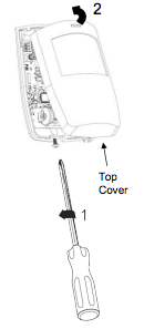
Unscrew the base screw on the SMCMT10-Z until loose. The screw can be retained in the product to secure cover when complete with installation.
Lift detector cover out from the base and off the lugs at the top.
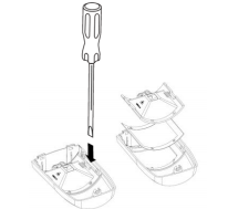
Loosen the printed circuit board (PCB) lock screw and remove the electronic assembly to gain access to the case mounting holes. Use the battery terminals as a hand hold in removing the electronics.
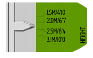
Find the base on the wall between 4.1 and 10 ft (1.5 – 3.1 m) from the floor. Recommended height is 2 m / 6′ 7″.
- For flat wall mounting use a minimum of 2 screws in positions A.
- For corner mounting use screws in positions B and/or C.
Drill holes in the base of the provided screw locator.
To complete the installation:
- Select the desired jumper settings. See “Setup and Jumper Selection” below.
- Add masking labels if required (see next section for an example).
- Replace the cover and tighten the screw in the base.
Note: Be sure the battery is inserted properly and/or the battery pull tab is removed to activate the SMCMT10-Z.
Setup and Jumper Selection
The SMCMT10-Z has two mechanical adjustments and three jumper switches. After selecting a mounting location, optimize the SMCMT10-Z.
Mechanical Adjustments 1 – Mounting Height
- On the left side below the tamper spring, find the PCB legend for mounting height adjustment.
- Loosen the PCB mounting screw by turning counterclockwise so the PCB may slide up and down.
- Use the plastic pointer, locate your mounting height and tighten the PCB screw. Selecting the proper height maximizes the sensors range and viewing area.
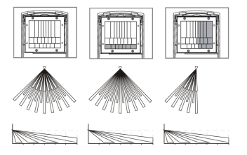
Mechanical Adjustment 2 – Viewing Range
This adjustment limits the SMCMT10-Z viewing area to a vertical curtain, removing short-range scanning, long-range scanning, or any combinations that suits the application. If you know the desired scanning zone(s) add masking to the inside surface of the Fresnel lens.
Note: Left to right: full range, short range removed, and ½ vertical range removed.
Switch Settings
There are three jumper switches at the top-left corner of the PCB. These jumpers assist in deice setup and its operation. Jumper Switch definitions:
- Input – selects the SMCMT10-Z input sensitivity. Default is STD.
- Walk Test – disables the wireless alarm to the Touchscreen. Default is OFF.
- Pulse – selects 50lbs or 100lbs pet immunity. Default is 100 lbs.
Selecting Sensitivity
The Input jumper selects between standard mode (STD) and a more sensitive option (Opt 2) which increases the SMCMT10-Z’s sensitivity. Use this switch only after the SMCMT10-Z has been powered up and completed its Learn Mode step. Not doing so tells the SMCMT10-Z to skip the Learn Mode function a production only feature.
Testing Coverage
To verify that the SMCMT10-Z detects all the areas: A. Set the Walk Test jumper to the ON position. This lets you walk in all areas of coverage to ensure the SMCMT10-Z detects a person’s movement. B. Make mechanical mounting adjustments as required to cover the open area. Setting Pet Immunity Depending on the pets inside the house, the SMCMT10-Z Pet Immunity is adjustable between 50 lbs or 100 lbs.
- For 50 lbs, move the Pulse jumper to the 50 position.
- For 100 lbs, move the Pulse jumper to the 100 position.