WARNING: CONSULT A PROFESSIONAL ELECTRICIAN PRIOR TO WORKING WITH ELECTRICAL WIRING.
Installation
This Relay Switch is designed to work as an independent device or as part of your home automation system. It mounts in a standard wall box and follows conventional wiring standards.
Power: 120 V AC, 60Hz
Supported Loads:
- 120V AC 1000W Incandescent
- 120V AC 1000W Halogen
- 120V AC 1000 W Fluorescent
- 120V AC 1000 VA Magnetic Low Voltage Transformer
- 120V AC 1000 VA Electronic Low Voltage Transformer
Operating Temperature: All load ratings are listed in accordance to an ambient temperature of 25 degrees Celsus (77 degrees Fahrenheit)
Communication: 2.5 GHz, 16-channel spread spectrum radio frequency, Zigbee HA
- Confirm that the intended installation location conforms with the following requirements:
- Wall box must meet box is requirements specified my the NES (National Electric Code)
- Installation will be completed according to national and local codes
- The load being controlled by the device does not exceed 1000 W
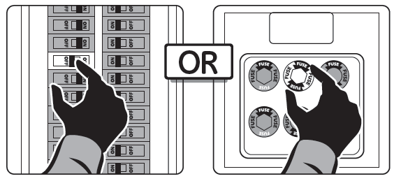
- To avoid SERIOUS INJURY or DEATH, turn OFF the local electrical power feeding the switch location. To disconnect power, turn off the breaker or remove the fuse from the fuse box. Verify that there is no power present using a voltage meter or test light.
- If you are retrofitting an existing switch using the Centralite Relay Switch, remove the existing switch. Note which wires are the Ground, Circuit Feed(HOT), Load(Switch Leg), and Neutral.
- Prepare the wires for connection by stripping off the insulation 5/8 of an inch.
- Connect the switch wires using the supplied wire nuts.
- Connect GREEN wire to GROUND
- Connect BLACK wire to HOT FEED
- Connect WHITE wire to NEUTRAL
- Connect RED wire to LOAD
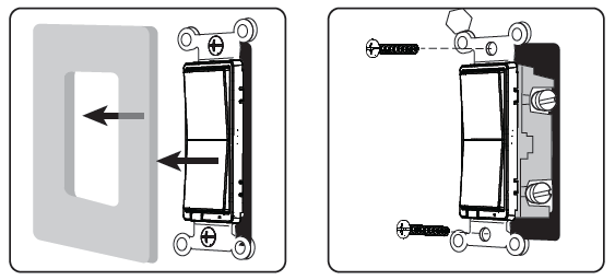
- Test all connections. Fold wires and push them neatly into the switch box. Align the Relay Switch in the switch box with the air gap oriented at the bottom of the Relay Switch. Using the supplied screws, secure the Relay Switch in the switch box.
- Verify that the Aire Gap switch is fully pushed in, then turn ON circuit breaker or replace the fuse.
- If the Relay Switch is installed properly, the top LED will blink slowly for 1000 seconds signifying that the devices is working as an independent local device.
- You should now be able to control the load by tapping the switch.
Pairing
- Disconnect power from the switch by pulling the air gap switch.
- While pushing the top of the Relay Switch, power the switch on by pushing in the air gap switch.
- After 2 seconds, the status LED will turn ON.
- Once the status LED is ON, release the button.
- The switch is now in pairing mode and is searching for the hub.