
CentraLite’s Pearl Thermostat is a revolutionary thermostat that combines contemporary aesthetics with easy-to-use controls. Utilizing a capacitive touch display, the thermostat delivers precise control and an unparalleled user experience. Features include a built-in power amplifier, up to a two-year battery life, and compatibility with most residential HVAC systems. With quick-connect terminals for tool-free wiring, installation is a breeze.
SpecificationsInstallationJoining to a TouchscreenResetting to Factory DefaultsTESTINGProgramming Guide
SPECIFICATIONS
- Easy compatibility with other manufacturers’ ZigBee HA 1.2 devices
- Long lasting two-year battery life (with typical operation) 4-AA batteries or commong wire can be used for 24VAC
- User friendly control
- Smooth front face with no physical buttons
- Slider control for precise setpoint changes
- Cool, heat, auto, off and em heat modes
- Proximity sensor to turn the device on from sleep mode
- Over-the-air updates for both the ZigBee and thermostat processor
- Easy compatibility with ZigBee HA 1.2 hubs and devices
- Controls up to two stages of heat and two stages of cool
- Auto configuration setup for HVAC system type
- Seven solid state AC unit controls
- Validation of AC unit relay closure
- Optional humidity sensor
- 0.1 degrees C temperature reports
- Built-in smart scheduler for use with coordinators with custom schedule
- Hold function to disable schedule on or off of the thermostat
- Large easy-to-read display
- Controls both electric and gas systems
- Built-in power amplifier for exceptional range
TECHNICAL SPECS
- Battery Type: Common Wire (24 VAC) and/or 4-AA batteries
- Battery Life: 2 years
- Dimension: 5.325″W x 4.125″H x 1.13″L
- Operating Temperature: 0° to 40°C
INSTALLATION
Before you begin installing your thermostat, please be advised that It is always a good practice to consult the owner’s manual for your HVAC system. If necessary, consult an HVAC technician to ensure proper installation.
Locating the Thermostat
If this is to replace an existing thermostat, just use the existing thermostat location.
If this is a new install follow these suggestions:
- Locate the thermostat about 5 ft. off the floor away from direct sunlight, lamps, radios, televisions, fireplaces, hot water pipes, or other heating or cooling sources.
- Do not locate the thermostat near doors to the outside or windows.
- Do not locate the thermostat in a damp area.
- Do not locate the thermostat in an area that lacks air circulation.
Remove the Existing Unit
- Switch OFF the electricity to the HVAC unit.
- Keep in mind that many thermostats use batteries as a back up source of power. To confirm the HVAC system is off, turn on the fan on the old unit. If the system does not come on, the power is off.
- Remove the cover to the existing thermostat
- Make a note of the terminal location for each wire connected to the thermostat wiring terminals.
- Wire colors are not standard so it is important to note the terminal label that each wire is connected to on the existing thermostat. It is ALWAYS a good idea to take a picture of the way your original thermostat is wired prior to removing the wires.
- While removing each wire from the existing thermostat wiring terminal, make sure to secure the wire so that it does not fall back into the wall.
- Once all wires are removed from the existing thermostat wiring terminal, remove the existing thermostat from the wall.
- Make sure to leave at least 3” of wire for each connection onto the PEARL thermostat wiring terminal.
- Remove 1/8” insulation from the end of each wire.
Installing the New Thermostat
Place each wire in the appropriate wire terminal.
- By default the PEARL thermostat comes with a wire jumper connecting the RH and RC power terminals. On most units only one power source is used and can be connected to both RH and RC. But if you have a millivolt system or other type of HVAC system it may require separate power sources for Heating and Cooling. In this case you will remove the jumper and separately power RC and RH.
- The PEARL thermostat can be powered by 4 AA batteries or by the power from the 24V off the HVAC unit if a Common(C) wire is available. Even if you use the common wire for power you should still install 4 AA batteries as a backup for the thermostat time clock.
The wiring terminal is labeled as follows:
| C | Y1 | G | W2 | W1/B | Y2/O | RC | RH | I1 | IC |
| C | Common |
| Y1 | Cool Control/Compressor |
| G | Fan |
| W2 | 2nd Stage Heat or Heat Pump auxiliary heat |
| W1/B | Heat Control/Heat Pump changeover (powered in heat mode) |
| Y2/O | 2nd Stage Cool Control/Heat pump changeover (powered in cool mode) |
| RC | Power From Cooling |
| RH | Power From Heating |
| I1 | Auxiliary Input Signal |
| IC | Auxiliary Input Common |
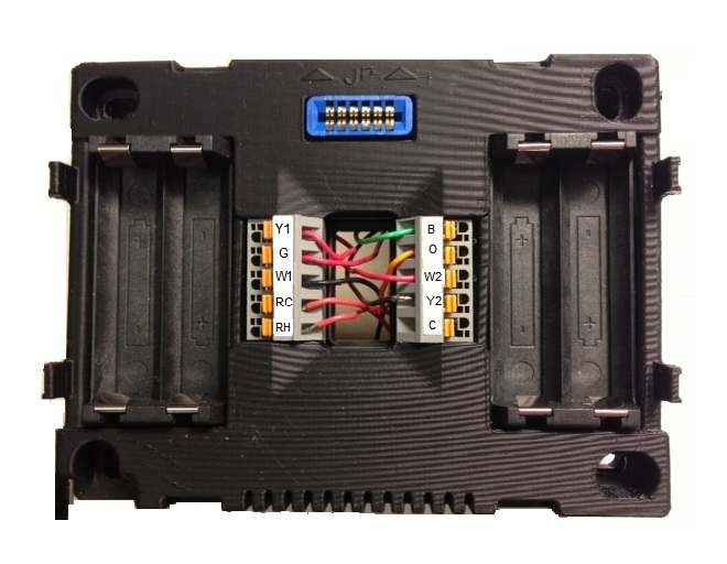
- Connect the wires to the terminal on the thermostat mounting plate.
- Hold the thermostat up to the wall in the desired position. Mark where the 4 holes are to be drill. Drill 4 3/16 holes for the wall anchors.
- Use the included wall anchors and screws to mount the thermostat securely onto the wall.
- Install 4 AA batteries into the battery compartment.
- Snap the outer cover onto the thermostat.
Configuring the Thermostat
The PEARL thermostat is designed to auto detect whether it is connected to a Heat Pump or a Non Heat Pump once the front cover is snapped onto the base plate
NOTE: A thermostat which shows “E0” is a thermostat which has not yet been connected to a “valid” system or one which has not yet been “programmed” yet. This “E0” is an indicator that the thermostat is in a factory default state. This “EO”status can be changed to a valid status by either programming the thermostat or by hooking up the thermostat to a valid system.
- From the factory the thermostat comes configured to work with single stage Cool/Heat, Single Speed Fan systems.
- If your HVAC system is different refer to the programming section by clicking the link at the bottom of this page to configure the thermostat for your system.
- If you have separate power for RH and RC then you will need to remove the factory installed jumper between RH and RC.
Once the thermostat is powered on, the ZigBee Status indicator will begin to flash indicating that the thermostat is ready to be joined to your home automation system. Return to the activation flow to pair your thermostat.
Once you have completed the installation process, return to the activation flow to add your device to your system.
JOINING TO TOUCHSCREN
To join your thermostat to your Touchscreen:
- Navigate to Settings > Home Devices > Thermostats > Add a Thermostat
- Press Next on the Touchscreen
- As thermostats are found, they will appear on the Touchscreen
- Once your thermostat has been discovered, select “Done” and follow the onscreen prompts
RESETTING TO FACTORY DEFAULTS
To default the thermostat, place the thermostat into programming mode by pressing between the hold button and the fan button. While continuing to hold between the hold button and the fan button, swipe down on the right slider until “01″ is displayed. When the “01” is displayed, it indicates you are in “programming mode.”
NOTE: Before you enter programming mode to program the thermostat, the device needs to be in an “off” state. To turn the thermostat off, press the “Mode” button until “Off” appears on the screen.
Use the + and – buttons to advance through the menu options listed below in the “Menu Options” list. Use the HOLD button to enter a menu option then use the + and – to set the appropriate value and then MODE to return to menu options.
Navigate to field “17″ and select option 11. This will set the thermostat to it’s factory default settings.
TESTING
Testing Thermostat Operation
- After completing any necessary configuration make sure the thermostat is in Cool mode by pressing the MODE button until Cool is displayed at the bottom of the screen.
- Make sure the system is not calling for Cooling by setting the setpoint several degrees above the room temperature. Then check the Fan operation by pressing the Fan button. When the Fan indicator is illuminated without the Auto indicator then air should blow from the unit.
- Now make sure the Fan mode is in Auto and run the setpoint temperature at least several degrees below the room tempera-ture. Give the thermostat at least 3 minutes to respond.
- Now change the system mode to HEAT. Allow the system at least 3 minutes to respond. The Heat(flame) mode symbol should illuminate and system should be blowing hot air.
PROGRAMMING
| Field Description | Field Number | Field Options |
| Display Celsius and Fahrenheit | 1 | 0 – Celsius 1 – Fahrenheit (Default) |
| Heat type (Heat pump / Non Heat pump) | 2 | 0 – Non Heat Pump (Default) 1 – Heat Pump |
| Heat source (Gas / Electric) | 3 | 0 – Electric (Default) 1 – Gas |
| Temperature Calibration | 4 | 0 – -2.5 – +2.5 Celsius 1 – -4.5 – +4.5 Fahrenheit Default – 0 |
| Set Minimum Heatpoint | 5 | 44 deg Fahrenheit/7 deg Celsius (Default) |
| Set Maximum Heatpoint | 6 | 86 deg Fahrenheit/30 deg Celsius (Default) |
| Set Minimum Coolpoint | 7 | 44 deg Fahrenheit/7 deg Celsius (Default) |
| Set Maximum Coolpoint | 8 | 86 deg Fahrenheit/30 deg Celsius (Default) |
| Set Minimum Deadband | 9 | 1.8 deg Fahrenheit/1.0 deg Celsius (Default) |
| Sequence of Operation | 10 | 0- Cool Only 1- Cool with reheat 2- Heat Only 3- Heat with reheat 4- Full Auto 5- Full Auto with reheat 6- Manual (Default) 7- Auto Only |
| EZ Mode | 11 | 0 – No 1 – Yes |
| Join Network | 12 | 0 – No 1 – Yes |
| Leave Network | 13 | 11 – Yes All Others – No |
| Rejoin Network | 14 | 0 – No 1 – Yes |
| Redirect System Type | 15 | 0 – No 1 – Yes Types Detected 04-HP Two Cool Two Heat 05 – Two Cool Two Heat FF – Invalid Relay Configuration |
| Reset | 16 | 0 – No 1 – Yes |
| Factory Reset | 17 | 11 – Yes All Others – No |
| Display Configuration and Network Settings | 18 | Order of Display: 1- PSOC Version Number 2- Ember Version Number 3- Heat Type 4- Heat Source 5- Temperature Calibration 6- Relays Detected 7- Network State 8- Network Channel 9-10- PanID |
| Reset Counter | 19 | 0 – 1 – Reset to 0 |