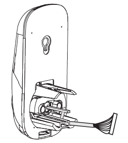
Unpack the Lock
The lock is packed representative of how it will install on the door.
Before installing the lock on the door:
A. Inside escutcheon
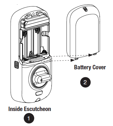
1. Loosen the screw (Phillips #2) holding the battery cover(The screw remains attached to battery cover).
2. Slide the battery cover up and out (note the two tabs at bottom of battery cover).
3. Remove the inside mounting plate (with gasket) from the back (door side) of the inside escutcheon.
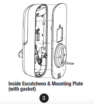
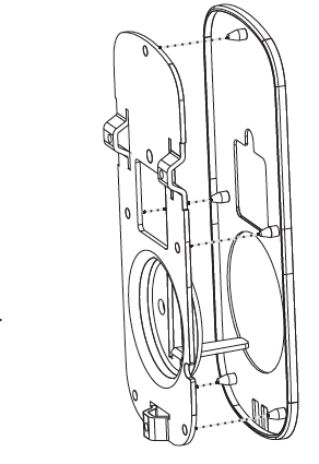
Ensure that gasket on Inside Mounting Plate is properly fitted. Note the positioning of the gasket’s five rubber nubs
B. Bolt
Note: Bolt ships with backset in 2-3/8″ position. If required, press small black button on underside of bolt and pull to extend to 2-3/4″ backset position.
C. The outside escutcheon (with gasket) remains assembled.
Installing the Lock
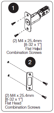
1. Install bolt in door.
NOTE: The bolt must be in a retracted (unlocked) position when installing the lockset.
Attach with two (2) M4 x 25.4mm [8-32 x 1″] screws supplied.
2. Install strike on the door frame, making sure to allow for the bolt to be centered in the strike.
3. Install outside escutcheon.
As you position the outside escutcheon, route the wire harness through 2-1/8″ diameter hole (Figure 3A).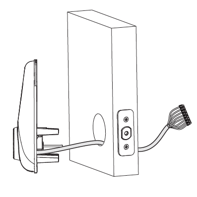
NOTE: Wire harness goes under bolt.
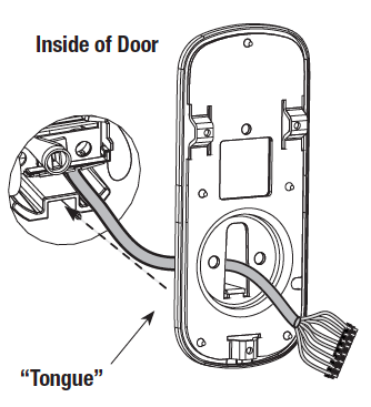
4. Holding the outside escutcheon flush to the door, position the inside mounting plate by first routing the wire harness through the mounting plate’s 1/2″ hole then inserting mounting plate “tongue“ into groove at bottom of outside escutcheon.
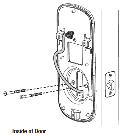
5. Secure both assemblies using (2) M6 x 59.5mm pan head machine screws (Fig. 4B), making sure that outside escutcheon is vertically aligned. Hand-tighten until snug.
Do not over-tighten.
CAUTION:
Position and bend cable, using care when assembling to ensure that the cable lies against the back recessed area of the inside escutcheon.
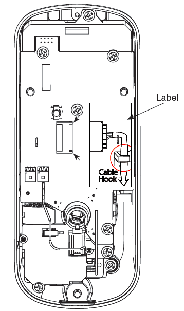
Use the cable hook (See label on circuit board) as shown in Figures 6A & 6C to prevent binding when installing the escutcheon over the mounting plate.
6. Attach cable assembly connector to the inside escutcheon PC board by lining up notches on top of cable connector to slots on PCB connector (Fig. 6B).
NOTE: Connector should be pressed in firmly using thumbs until completely seated.
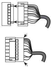
Proper position is indicated by arrows on PCB 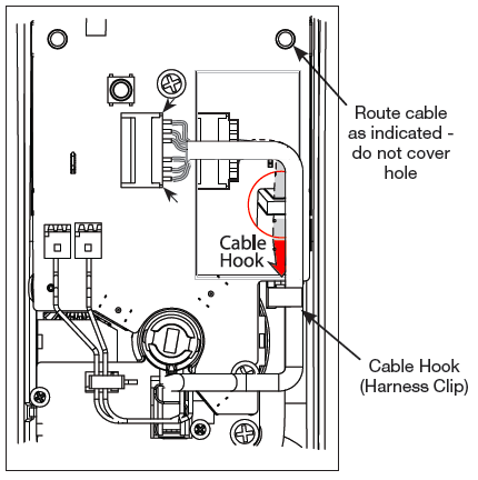
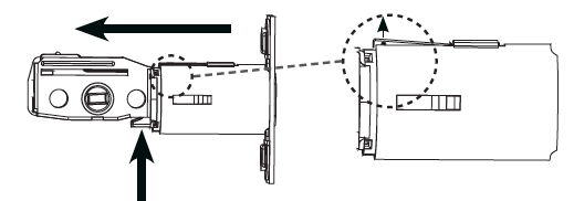
7. Install inside escutcheon on inside mounting plate.
Note: the horizontal orientation of the tailpiece (Fig. 7) as you insert the inside escutcheon;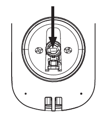
the thumbturn should be vertical.
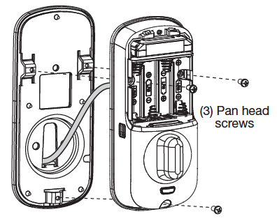 8. Install and secure using (3) M4 x 8mm [8-32 x 5/16″] pan head screws through the inside escutcheon into the mounting plate.
IMPORTANT: Before installing the batteries, test the mechanical operation of the lock by operating the thumbturn. The movement of the bolt should be smooth and unobstructed.
If operation is not smooth, review the previous steps to ensure proper installation.
NOTE: The bolt must be in a retracted (unlocked) position prior to installing the batteries.
9. Insert four (4) AA alkaline batteries. The lock will flash, beep several times and respond with the vocal prompt: 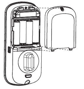
“Welcome to Yale Real Living”.
When activating the lock for the first time, the lock will adjust for proper handing.
Note: Refer to programming instructions in following section prior to completion of next step (10).
10. Install battery cover and tighten Phillips head screw.
Lock Activation
The touchscreen can be activated in several ways:
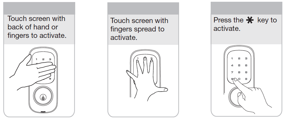
OPERATION
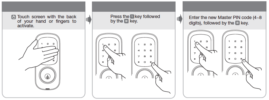
1. Touch the screen with the back of your hand or fingers to activate .
2. Press the “1” key.
Lock Response: “Register Master Code; press the “#” key to continue.”
3. Press the “#” key.
Lock Response: “Enter a 4 to 8 digit PIN code followed by the pound key.”
4. Enter new 4-8 digit Master PIN code followed by the “#” key.
Lock visually confirms PIN code selection, announces “Registered”.
PIN Code Structure
Maximum number of user codes is 250 with Network Module; without Network Module, maximum is 25 user codes.
Set Up User PIN Codes
Set Up User PIN Codes
User PIN Codes can only be programmed through the Master PIN Code*.
1. Touch the screen with the back of your hand or fingers to activate.
2. Enter the 4-8 digit Master PIN code followed by the “#” key.
Lock Response: “Menu mode, enter number, press the “#” key to continue.”
3. Enter “2” followed by the “#” key.
4. Enter “1” followed by the “#” key.
5. Enter the User Number to be registered (1-25) followed by the “#” key.
6. Enter a 4-8 digit PIN code for the User number followed by the “#” key.
7. To continue adding users press the “#” key.
8. Press the “#” key to complete the process and conclude the programming session.
Note: When registering User codes, the code must be entered within 20 seconds or time expires. Lock Response: “Time expired”, no codes are registered and the process must be re-started.
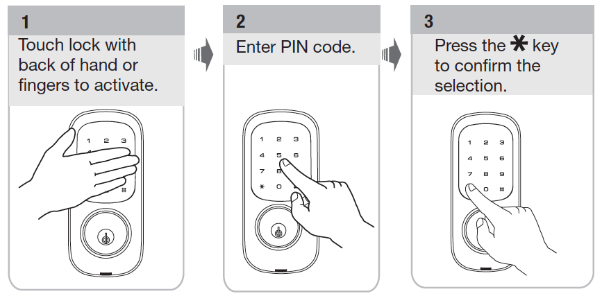
Opening Door with PIN Code
Troubleshooting
Cycle the lock in both the locked and the unlocked positions. If problems are found:
| Symptom | Suggested Action |
| Door is binding | a. Check that door and frame are properly aligned and door is free swinging.b. Check hinges: They should not be loose or have excessive wear on knuckles. |
| Bolt will not deadlock | a. Check for sufficient clearance of the bolt within the strike-side jamb. Correct this by increasing the depth of the pocket for the bolt.b. Check for misalignment of bolt and/or strike which may be preventing bolt from properly entering the strike. With the door open, extend and retract the bolt; if it is smooth, check the strike alignment. |
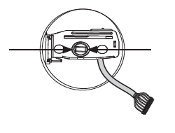
| Bolt does not extend or retract smoothly | a. Bolt and strike are misaligned, see above.b. Check the backset of door relative to adjustments already made to bolt.c. Verify proper door preparation and re-bore holes that are too small or misaligned.d. Verify keypad wire harness is routed under the bolt (see Fig. A).
e. Verify bolt is installed with correct side up (Fig. A). |
| Keypad numerics are scrolling | Remove interior escutcheon and check to ensure that the wire harness lies flat against the back recessed area and is properly routed along the side of the escutcheon and tucked under the plastic cable guide. |
| Lock does not respond – door is open and accessible. | The touchscreen will become active when pressed with the back of hand or fingers in at least 3 areas simultaneously.Use a larger area of the hand or fingers and verify contact with at least 3 areas.If touchscreen numbers are visible, check to see if they respond when pressed.Check batteries are installed and oriented correctly in the battery case.
Check batteries are in good condition; replace batteries* if discharged. Check to see if touchscreen wire harness is fully connected and not pinched. |
| Lock does not respond – door is locked and inaccessible. | Lock may be in Privacy mode (set from inside room). Mechanical key will grant access.Batteries may be completely discharged.Use mechanical key to gain entry and replace batteries*. |
| The unit is on for a while, and then shows no reaction. Lights dim. | The batteries do not have enough power. Replace the batteries*. |
| Unit chimes to indicate code acceptance, but the door will not open. | Check to see if there is an existing lock device on the door.Check the door gaps for any foreign objects between door and frame.Check that the wire harness is firmly connected to the PCB. |
| Unit operates to allow access, but will not automatically re-lock. | Automatic Re-Lock has been disabled; enable in Menu Mode Advanced Settings.If low battery indicator is lit, replace batteries*. |
| PIN codes will not register. | Registration/management of PIN codes is set by the authority of Master Code.The Master PIN code must be registered prior to adding any users.PIN codes must consist of 4 to 8 digits to register.The same PIN code cannot be used for multiple users.
Contact the Master user. User codes must be entered within 5 seconds (while the touchscreen is active) or the process will have to be restarted. The star (*) or pound (#) can not be used as part of the PIN code. |
| Upon entering a PIN code and pressing the star (*) key, the unit displays an “invalid code” error or the lock times out without responding. | All Code Lockout Mode is enabled.Only the Master Code can enable All Code Lockout Mode.Contact the Master user. |
| Upon entering a PIN code and pressing the (*) key, the red padlock icon appears and there are different tones. | Check to see if lock is set** at All Code Lockout Mode.Setting/managing All Code Lockout Mode is done through Master Code only. Contact the Master user. |
| The unit operates, but it makes no sound. | Check to see if Silent Mode is enabled (pages 8, 11). |
| The unit responds “Low Battery” | This is the voice alarm alerting that it is time to replace the batteries. Replace all four (4) batteries with new AA Alkaline batteries*. |
| Upon entering a PIN code and pressing the star (*) key, the unit responds “Wrong number of digits.” | The digits entered were incorrect or incomplete. Re-enter the correct code. |
Pairing Defaulting Deleting Programming