Auxiliary Input Wiring
Remember! If your application does not require the auxiliary input, be sure to set DIP switch SW2 to OFF and to short the input terminals together with a piece of jumper wire.
Connect the auxiliary detector’s alarm contacts across the MCT-302 auxiliary input terminals.
If the auxiliary input of the MCT-302 is defined as a Normally Closed (N.C.) type (SW2 set to OFF), series connected N.C. sensor contacts must be used exclusively. An E.O.L. resistor will not be required.
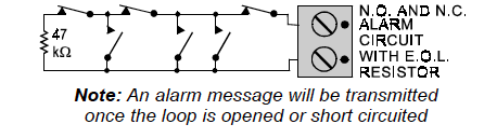
If the auxiliary input is defined as an E.O.L. type (SW2 set to ON), Normally Closed (N.C.) as well as Normally Open (N.O.) sensor contacts can be used. A 47kΩ E.O.L. resistor must be wired at the far end of the zone loop.
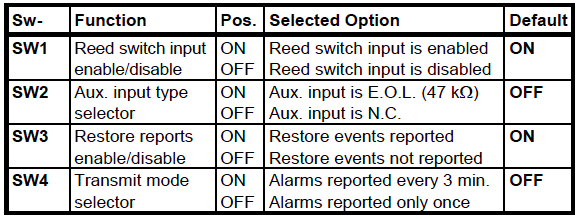
The Function Switches
Switch Tasks
The MCT-302 has a 4-position DIP switch function selector. Each switch lever allows you to select one of two options.

Setting the Switches
Set the function switches as desired prior to applying power. Use a ball point pen or another pointed object to shift the switch levers. The ON position is indicated by the arrow on the switch body.