")
The in-wall relay controls lighting in the home by providing remote ON/OFF functionality to a connected in-wall lighting device. Compatible with hard-wired incandescent, LED, xenon, halogen and fluorescent lighting. The on/off switch replaces your current light switch, uses your existing wiring and provides ZigBee wireless and in-wall control of overhead lighting. The contemporary switch includes a blue LED indicator light to easily locate the switch in a dark room. It features a gloss white finish that matches modern wall plates.
Specifications Installation Pairing Resetting
Features and Specifications
- Turn ON/OFF or DIM lighting manually or remotely via the ZigBee controller
- May be used in single pole installation or with up to two Jasco auxiliary switches for 3-way or 4-way wiring configurations
- Interchangeable Paddle Switch
- Over the air updates
- Energy monitioring – device can report wattage and kilowatt hours
- Uses a standard, decorative-size waill plate for single gang installations
- Blue LED indicates switch location in a dark room
- LED status indicator
- ZigBee HA 1.2 Certified for simple pairing and integrated home automation
- Screw Terminal Installation — requires wiring connections for Line (Hot), Load, Neutral, and Ground. Traveler wire required only for 3-way or 4-way installation
Specifications
- Battery Type: N/A (120VAC Direct Wire)
- Battery Life: N/A
- Dimension: 1.75(D) x 2.125(W) x 4.125 (H)
- Operating Temperature: Exterior: Normal temp: 77° F
Installation
WARNING: CONSULT A PROFESSIONAL ELECTRICIAN PRIOR TO WORKING WITH ELECTRICAL WIRING.
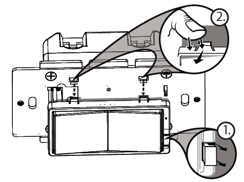
Changing the Color of the Paddle
- Lift the Air Gap tab at the base of the paddle.
- Push side tabs in on one side and then the other to release paddle. Lift the cover up and off.
- Simply put the new paddle onto the switch by inserting the air gap and side tabs and snapping securely into place.
Installation
This switch may be used in new installations or to replace an existing wall switch. It may be used by itself for 2-way control (one switch & one load), add one Jasco Auxiliary Switch for 3-way control (two switches & one load) or add two Jasco Auxiliary switches for 4-way control (three switches & one load). When used by itself for 2-way control, please make sure that the screw terminal for the traveler wire is insulated (Do Not Remove the tape over the terminal if you are not using the traveler connection.
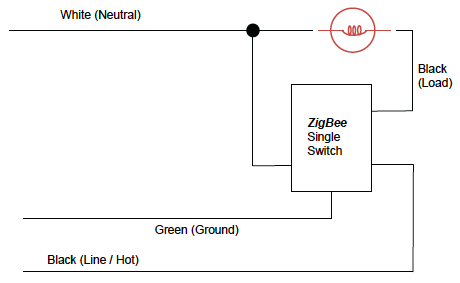
Two-Way Control
Single switch wiring using one primary switch
Single, Dual And Triple Gang Boxes
When installing the In-Wall On/Off switch in multiple gang boxes it may be necessary to break off one or both of the scored tabs on the front yoke. This does not affect the electrical rating of the switch.
Observe Important Wiring Information
Important: This switch is rated for and intended to only be used with copper wire.
The home’s electrical wires may be attached to the screw terminals or inserted into the holes in the back of the switch enclosure and clamped in place by tightening the screw terminals. Always follow the recommended wire strip lengths when making wiring connections.
Wire Gauge Requirements
Use 14 AWG or larger wires suitable for at least 80° C for supply
Line (HOT), Load, Neutral, Ground and Traveler connections.
Wire strip length:
• For attachment to screw terminals: Strip insulation 1″ (25mm)
• For attachment using the enclosure’s holes:
Strip insulation 5/8″ (16mm)
UL specifies that the tightening torque for the screws is 14 Kgf-cm (12 lbf-in).
Single Switch Wiring
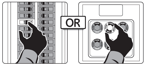
- Shut off power to the circuit at circuit breaker or fuse box.
! Warning: Verify power is OFF to switch box before continuing.
- Remove wall plate.
- Remove the switch mounting screws.
- Carefully remove the switch from the switch box.
DO NOT disconnect the wires.
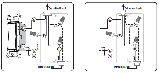
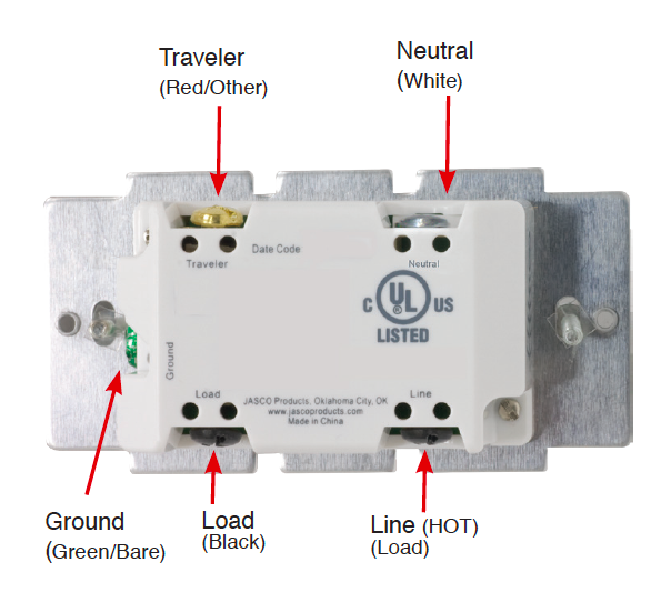
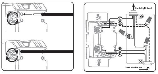
- There are up to five screw terminals on the switch;
these are marked
A. LINE (Hot) — Black (connected to power)
B. Neutral — White
C. LOAD — Black (connected to lighting)
D. GROUND — Green/Bare
E. TRAVELER — Red/Other
Match these screw terminals to the wires connected to the existing switch.
- Disconnect the wires from the existing switch. Be careful to label wires according to the previous terminal connection.
The Jasco Auxiliary switch is required for Multi-Switch 3-way or 4-way installations.
Connecting the traveler terminal of this switch to a standard, non-Jasco switch will cause damage or result in improper function. If this switch is a part of a 3-way or 4-way multi-switch installation, do not connect the traveler wire or apply power until Jasco Auxiliary switches are correctly installed. For more information on 3-Way or 4-Way installations, view the manual or quick-start guide that comes with the Jasco Auxiliary switch.
Connect the green or bare copper ground wire to the GROUND terminal.
Connect the black wire that goes to the light to the terminal marked LOAD.
Connect the black wire that comes from the electrical service panel (Hot) to the terminal marked LINE.
Connect the white wire to the neutral terminal.
Note: UL specifies that the tightening torque for the screws is 14 Kgf-cm (12 lbf-in).
The Traveler terminal is only used for 3-way or 4-way wiring and should remain insulated if the switch is being installed in a 2-way system (one switch & one load).
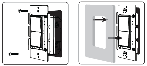
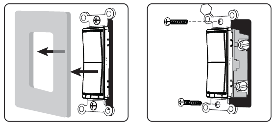
- Insert Switch into the switch box being careful not to pinch or crush wires.
- Secure the switch to the box using the supplied screws.
- Mount the wall plate.
- Reapply power to the circuit at fuse box or circuit breaker and test the system.
Basic Operation
The connected light can be turned ON/OFF in two ways:
- Manually from the front panel of the in-wall switch
- Remotely with a ZigBee Controller
Manual Control
The Front Panel Rocker Switch allows the user to:
Turn ON/OFF the connected lighting.
- To turn the connected lighting ON: Tap the top of the rocker.
- To turn the connected lighting OFF: Tap the bottom of the rocker.
Pairing
- From your ZigBee Controller’s interface, choose to add lighting device and enter Locating/Pairing mode as instructed by the controller.
- Restore power to the switch at the circuit breaker
- Network Pairing Begins Automatically: LED Status Indicator Blinks as the device automatically scans for a compatible network controller to pair with.
- After the switch is located and paired to the ZigBee network, the LED Status Indicator will stop blinking and the switch will appear in your controller’s menu. Setup the switch as a dimmer control and title the switch in a way that will be easy to identify. The switch is now paired to the ZigBee network and can be controlled remotely. Note: LED Status Indicator stops blinking if a timeout occurs: Auto-Scan mode will eventually time out if the device has not joined a ZigBee network. Press the front panel pushbutton on the module to restart pairing process following timeout. Time out will only occur twice, if the device is not paired before the second time out, manual reset will be required before pairing. Please refer to the following section for details.
LED Parameters
To assist with locating the switch in a dark room, the LED glows blue when the light switch is turned OFF.
To turn LED off:
Tap top rocker (ON Switch) 3x quickly and then tap bottom rocker (OFF Switch) 1x
To restore LED:
Follow the same series of button presses used to disable the LED to restore
Pairing
You can add lights when you activate Touchstone or at a later time. If you want to add a light that was not included with the original Touchstone package, make sure your service provider supports it.
To add lights, click Settings on the tool bar to display the settings menu.
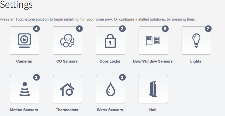
Click lights to display the light setting page.
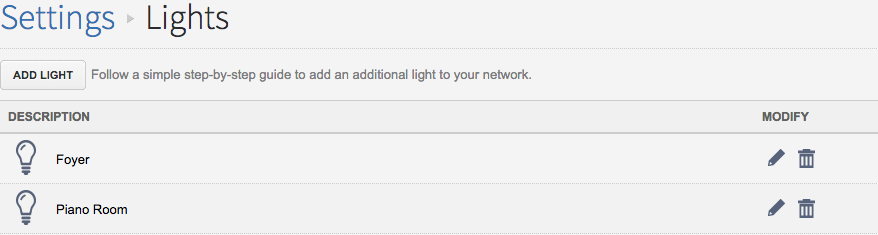
Click Add Light and follow the onscreen prompts.
Resetting
From the Hub
From your controller or hub interface, choose to remove or delete the lighting device as instructed. The device will be removed from the ZigBee network following indication from your controller. All configuration parameters will be reset after the device is removed from the network.
Manually
To manually reset and remove the device from the ZigBee network, Tap Top of Rocker (ON Switch) 10x quickly (short presses)